


联系我们
-
中国山东省潍坊市高新区软件园3-2-1003
- +8615095247272
- sales@uleengen.com
-


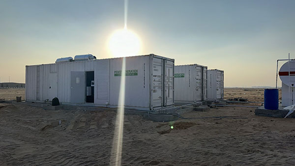
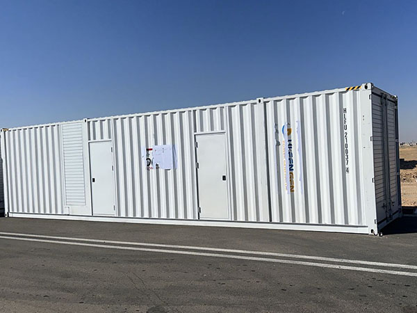
山东优力发电机公司提供的1600千伏安康明斯柴油发电机组为中东某空军基地供电,在高温环境下可靠运行。


打造“空中长城”:六台1600千伏安康明斯发电机组为空军基地构建电力堡垒
在现代战争中,空中力量是决定胜负的关键因素,而空军基地则是这股力量的“鹰巢”。从飞行控制塔内的精确雷达导航,到机库内的地面维护作业,再到战斗机起飞所必需的各种照明和导航系统——电力是维持空军基地运转的生命线。面对现代战争的高机动性和高强度特点,以及极端自然灾害和战场环境的潜在威胁,传统公用电力供应的固有脆弱性日益凸显。
为了全面解决战备可靠供电的关键挑战,并构建一个具有“和平时期和战时能力一体化、相互冗余”的强大电力系统,某重要空军基地已投入使用六台1280千瓦康明斯大功率柴油发电机组作为其核心主电源。这六台“电力巨兽”的部署标志着该基地电力保障能力的重大升级,使其从纯粹的“支援型”模式转变为完全的“作战型”模式。
一、动力核心:排量为 50.3 升的工业心脏
该项目所部署的发电机组的核心动力装置是康明斯KTA50-GS8柴油发动机。作为康明斯动力产品组合中的经典之作,这款发动机采用V型16缸布局、四冲程循环和涡轮增压中冷设计,单台排量高达50.3升。
 |
 |
 |
发动机通用数据
Type……………………………………………………………………………………………………………………………………………. 4-Cycle; 60° Vee; 16-Cylinder Diesel
Aspiration…………………………………………………………………………………………………………………………………….. Turbocharged & Low Temp. Aftercooled
Bore x Stroke ………………………………………………………………………………………………..— in x in (mm x mm) 6.25 x 6.25 (159 x 159)
Displacement ………………………………………………………………………………………………………………— in3 (liter) 3067 (50.3)
Compression Ratio………………………………………………………………………………………………………………………. 14.9 : 1
干重
Fan to Flywheel Engine…………………………………………………………………………………………… — lb (kg) 11820 (5360)
湿重
Fan to Flywheel Engine…………………………………………………………………………………………… — lb (kg) 12485 (5662)
旋转部件的转动惯量
- with FW 6009 Flywheel ………………………………………………………………………………. — lbm • ft2 (kg • m2) 271 (11.4)
- with FW 6017 Flywheel……………………………………………………………………………….. — lbm • ft2 (kg • m2) 515 (21.7)
飞轮壳体后表面重心 (FH 6024) 47.5 英寸 (1206 毫米)
Center of Gravity Above Crankshaft Centerline……………………………………………………………… — in (mm) 11.0 (279)
Maximum Static Loading at Rear Main Bearing………………………………………………………………. — lb (kg) 2000 (908)
发动机支架
块体后表面最大弯矩:4500 (6100) 磅·英尺 (牛·米)
排气系统
Maximum Back Pressure …………………………………………………………………………………. — in Hg (mm Hg) 2 (51)
空气导入系统
最大进气限制
- with Dirty Filter Element ……………………………………………………………………………. — in H2O (mm H2O) 25 (635)
- with Clean Filter Element ………………………………………………………………………….. — in H2O (mm H2O) 15 (381)
冷却系统 (低温后冷却)
Coolant Capacity — Engine Only………………………………………………………………………… — US gal (liter) 43.5 (165)
发动机外部最大冷却液摩擦头
— 1500 rpm [高流量]…— psi (kPa) 10 (70)
— 1500 rpm [低流量]— psi (kPa) 5 (35)
发动机曲轴中心线以上冷却液最大静压头 60 英尺 (18.3 米)
标准恒温器调节范围 — 高流量(夹套)— °F (°C) 180 至 200 (82 至 93)
— Low Flow (Aftercooler)………………………………. — °F (°C) 150 – 175 (66 – 79)
最小压力上限(适用于静压头小于 2 米 [6 英尺] 的冷却系统)— psi (kPa) 14 (96)
过载功率/主功率最高顶部水箱温度—°F (°C) 220 / 212 (104 / 100)
后冷却器目标冷却液入口温度(环境温度 77 °F (25 °C)) 130 (55)
后冷却器最高冷却液温度 — 过载功率/主功率 — °F (°C) 160 / 150 (71 / 66)
润滑系统
Oil Pressure @ Idle Speed……………………………………………………………………………………….. — psi (kPa) 20 (138)
@ Governed Speed……………………………………………………………………………… — psi (kPa) 50 – 70 (345 – 483)
Maximum Oil Temperature …………………………………………………………………………………………… — °F (°C) 250 (121)
Oil Capacity with OP 6027 Oil Pan : High – Low……………………………………………………… — US gal (liter) 47 – 39 (178 – 148)
系统总容量(含旁路滤波器) 54 (204) 美制加仑
燃油系统
Type Injection System……………………………………………………………………………………………………………………………… Direct Injection Cummins PT
PT燃油喷射泵最大阻力 — 燃油滤清器清洁时 — 单位为英寸汞柱 (mmHg) 4.0 (102)
— 燃油滤清器脏污…… — 气压 (毫米汞柱) 8.0 (203)
喷油器回油管最大允许扬程
(由摩擦水头和静水头组成)— 单位为英寸汞柱(毫米汞柱)6.5 (165)
Maximum Fuel Flow to Injection Pump……………………………………………………………. — US gph (liter / hr) 151 (570)
如此惊人的排量转化为卓越的动力储备。凭借1200kW的备用功率,这套动力系统能够满足基地内任何突如其来的电力需求。无论是为战斗机起飞时高强度的导航雷达扫描提供动力,还是同时驱动一组燃油输送泵,这台“动力心脏”都能保持1500转/分的恒定转速,并提供极其平顺的扭矩输出。此外,其配备的PT燃油泵和STC(阶梯正时控制)技术确保了最佳的燃油燃烧效率和经济性,即使在高温或高海拔等严苛工况下,也能释放澎湃动力。
电气系统
Cranking Motor (Heavy Duty, Positive Engagement)…………………………………………………………………………………………… — volt 24
Battery Charging System, Negative Ground………………………………………………………………………………………………… — ampere 35
Maximum Allowable Resistance of Cranking Circuit…………………………………………………………………………………………… — ohm 0.002
最低推荐电池容量
- Cold Soak @ 50°F (10°C) and Above………………………………………………………………………………………………… — 0°F CCA 1280
- Cold Soak @ 32°F to 50°F (0°C to 10°C)……………………………………………………………………………………………. — 0°F CCA 1800
- Cold Soak @ 0°F to 32°F (-18°C to 0°C)…………………………………………………………………………………………….. — 0°F CCA 1800
冷启动能力
辅助(带冷却液加热器)冷启动10秒内所需的最低环境温度为:50°F (°C)
Minimum Ambient Temperature for Unaided Cold Start………………………………………………………………………………….. — °F (°C) 45 (7)
性能数据
所有数据均基于:
- 发动机的运行包括燃油系统、水泵、润滑油泵、空气滤清器和排气系统。
消音器;不包括电池充电交流发电机、风扇和可选驱动组件。
- 发动机使用符合 ASTM D975 标准的 2-D 级燃料。
- ISO 3046 第 1 部分,标准参考条件:
气压:100 千帕(29.53 英寸汞柱) 气温:25 摄氏度(77 华氏度)
海拔:110米(361英尺) 相对湿度:30%
Steady State Stability Band at any Constant Load ……………………………………………………………………………………………….. — % +/- 0.25
典型发电机组的估计自由场声压级;
Excludes Exhaust Noise; at Rated Load and 7.5 m (24.6 ft); 1500 rpm………………………………………………………. — dBA 92.4
从排气管出口中心线水平向上 45° 1 米处的排气噪声………………………………….. — dBA N.A.
二、电源质量:守护精密电子设备的“纯正血统”
空军基地集成了大量精密电子设备,例如着陆制导雷达、通信导航系统和指挥自动化系统。这些设备对电源质量极其敏感;即使是微小的电压波动也可能导致数据错误或设备损坏。
这六台发电机组均配备了斯坦福S7L1D-C41系列无刷交流发电机。其H级绝缘等级和2/3节距绕组设计不仅确保了在持续高温下的安全运行,而且还将电压波形畸变率保持在极低的水平。数据显示,该交流发电机的电话谐波系数(THF)小于2%,电话干扰系数(TIF)小于50,完全符合军用通信电源的严格标准。这意味着这些设备提供的不仅仅是电力,而是符合军用规格的“纯正”电源,确保基地的“大脑”和“眼睛”始终保持警觉和敏锐。
三、集群操作:并行技术实现“N+1”冗余备份
单台发电机1280千瓦的输出功率固然令人印象深刻,但由六台这样的发电机组成的电力阵列的价值远不止于此。通过先进的自动化并联控制系统,这六台发电机构成了一个高度智能化的电力矩阵。
在和平时期,该系统会根据基地的负荷需求自动计算最佳运行策略。例如,在夜间低负荷时段,系统仅启动一到两台发电机,使其在经济负荷范围内高效运行,从而显著节省燃料和维护成本。相反,在战时或高度戒备状态下,该系统可以实现“零等待”全功率输出。
这项“并行运行”技术的核心在于负载均衡和自动同步。控制系统利用高速微处理器实时监测每个单元的电压、频率和相位。一旦电网发生故障——无论是停电还是遭受敌对攻击——这六个单元都能迅速启动;通过自动同步控制器,它们能够执行精确的毫秒级电路闭合,将六股强大的电流无缝汇入主母线。该型号最大的优势在于其“N+1”冗余备份配置:即使其中一个单元因维护而离线,其余五个单元仍能保障对战备至关重要的电力供应,从而彻底消除单点故障导致全基地断电的风险。
IV. 战斗准备和适应性:经受住了“战场考验”的设计
军用装备的核心性能指标是可靠性。从一开始,该电源系统的设计就充分考虑了其对严格军用标准的适应性:
环境适应性:考虑到空军基地可能部署在不同地理区域的实际情况,这台发电机组具备卓越的环境适应性。其冷却系统采用高流量冷却液通道和二氯乙酸(DCA)添加剂,可承受高达 45°C 的高温环境。此外,该机组还配备了高功率 24V 电启动系统,即使在极低温度条件下也能确保发动机近乎瞬时且成功启动。
抗冲击性和防护性:该设备设计用于承受地震力(具体而言,水平加速度为0.2g,垂直加速度为0.1g)。通过应用严格的紧固原理和高强度底座框架,即使受到空中轰炸的振动或附近弹药库爆炸产生的冲击波的影响,该系统也能保持其结构完整性和运行稳定性。
电磁兼容性 (EMC):作为军事设施的关键组成部分,电磁隐蔽性和兼容性至关重要。该电源系统在其设计和制造阶段严格遵循军用规范(例如 GBBZ 24974-2012),以严格抑制电磁辐射。这确保了发电机组在运行过程中不会干扰基地的敏感通信和探测设备,同时最大限度地降低其被敌方电磁侦察系统探测到的可能性。
上一个 如何为建筑工地选择主用发电机


